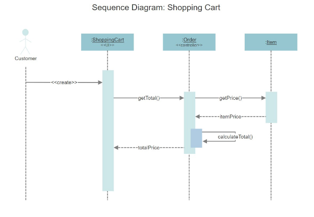

It's shown by an arrow going from a lifeline to an endpoint, a filled circle or an x. It can be shown by an arrow with an x at the end.Ī message sent from an unknown recipient, shown by an arrow from an endpoint to a lifeline.Ī message sent to an unknown recipient. This is a message that destroys an object. Similar to a return message, it's depicted with a dashed line and an open arrowhead that points to the rectangle representing the object created. This is a message that creates a new object. Like synchronous messages, they are drawn with an arrow connecting two lifelines however, the arrowhead is usually open and there's no return message depicted.Ī reply message is drawn with a dotted line and an open arrowhead pointing back to the original lifeline.Ī message an object sends to itself, usually shown as a U shaped arrow pointing back to itself. It's usually drawn using a line with a solid arrowhead pointing from one object to another.Īsynchronous messages don't need a reply for interaction to continue. Ī synchronous message requires a response before the interaction can continue. Place the condition for exiting the loop at the bottom left corner in square brackets. When that object's lifeline ends, you can place an X at the end of its lifeline to denote a destruction occurrence.Ī repetition or loop within a sequence diagram is depicted as a rectangle. Objects can be terminated early using an arrow labeled ">" that points to an X. Lifelines are vertical dashed lines that indicate the object's presence over time. Asynchronous messages are sent from an object that will not wait for a response from the receiver before continuing its tasks. Use half-arrowed lines to represent asynchronous messages.

Messages are arrows that represent communication between objects.

When an object is busy executing a process or waiting for a reply message, use a thin gray rectangle placed vertically on its lifeline. This is represented with the created word on top of a dotted arrow.

Use the UML object symbol to illustrate class roles, but don't list object attributes.Īctivation boxes represent the time an object needs to complete a task. This message is used when we create a new object in the sequence diagram. In the user authentication process we describe, the messages show how a user enters information into the browser to gain access to the webpage and how the web browser will then cross-check credential to the designated application.Start Now Basic Sequence Diagram NotationsĬlass roles describe the way an object will behave in context. What information is passed from one object to another? The other set of components you must identify are the messages the objects will send. Solid line without arrow-> Dotted line without arrow-> Solid lines have arrows-> The dotted line has an arrow-x: Solid line crossing arrow-x: Dashed cross arrow-) Solid line with an open arrow at the end (async) The version is too high and is not supported by most markdown editors.-) Dotted line with a open arrow at the end (async) The. title: Diagram title participant A participant B A->B: Normal line B->A: Dashed line. The objects, sometimes called actors, are the principal players that perform tasks and send messages.įor example, in a login sequence, two of the objects would be the potential visitor or user and the login page a visitor uses to interact with the platform they’re attempting to log into. A Confluence macro for creating sequence diagrams from plain-text. The first necessary set of components are the objects. To accomplish these goals, you must first identify the components of your system that should be diagrammed. Map out a real or hypothetical scenario that has many different components. See how objects and components interact with each other in sequence to complete a process. However, the majority of sequence diagrams will communicate what messages are sent and the order in which they tend to occur. The focus is more on the order in which messages occur than on the message per se. In UML, the lifeline is represented by a vertical bar, whereas the message flow is represented by a vertical dotted line that extends across the bottom of the page. It helps in envisioning several dynamic scenarios. Model how a complex procedure or system operates. As mentioned the aim of a sequence diagram is to define event sequences, which would have a desired outcome. The sequence diagram represents the flow of messages in the system and is also termed as an event diagram. You can accomplish several critical tasks with a sequence diagram.


 0 kommentar(er)
